Approx. Time: 3 hrs.
*Hardware and Tools Needed: (VDO Playback Tach)
10 - Feet Electrical Wire
1 - Wire Stripper / Pliers
10 - 3/16" x .75" Rivits
1 - Rivit Gun
2 - Female Spade Wire Connector
1- 12" x 12" x .125" Aluminum Sheet
1 - Jig Saw With Aluminum Cutting Blade
1 - Regular Pliers
1 - Electric Or Cordless Drill
1 - 3/16" Drill Bit
1 - 1/2" Drill Bit
1 - 2-Way 12v Electrical Toggel Switch
1 - 12v Battery
3 - Scotch-Locks (Optional)
1 - 1/2" Round Red 12v Light
Soldering Iron
Solid Core Solder
Solder Paste
Electrical Tape
Silicon (Optional)
Step 1:
Remove Stock Tach/Speedometer and Hardware.
Step 2:
Decide On Location And Mount Battery For Tach Opperation. Also, Decide On And Mount Electrical Toggel Switch.
Step 3:
Create Pattern To Cover Dash Hole And Used To Cut Out Aluminum. Two Pieces Will Be Needed.
Step 4:
Cut 3.5" Hole (OD Of VDO Tach May Vary) Centered In Both Plates.
Step 5:
Use Drill And 3/16" Drill Bit To Drill Holes Along Inside Edge (Approx. 1.00" From Edge) In Both Plates. Make Sure These Holes Don't Interfear With The Dash. You Want To Make Sure These Holes Are INSIDE Of The Hole Already In The Dash As To Not Drill Holes In The Plastic.
Step 6:
Take Back Off Of VDO Tach And Remover Rubber Seal. Place Rubber Seal On The Plate That Will Be Placed On The Outside Of The Hood. This Will Help Absorb Any Vibration.
Step 7:
Line Inside Of Outer Plate With Weatherstripping. This Will Help Prevent Any Scratching To The Plastic Dash From The Aluminum Plate.
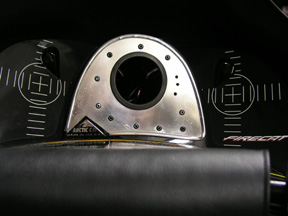
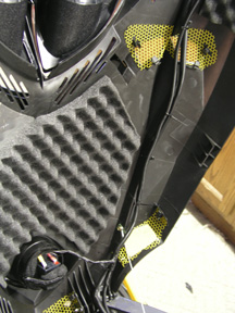
Step 8:
Place Plate With Rubber On Outside Of Dash Hole And The Other Plate On Inside Of Dash Hole And Use Holes From Step 5 To "Sandwich" The Two Plates And The Dash Together With The Rivits. See Picture 1.
Step 9:
Remove Mounting Ring From VDO Tach.
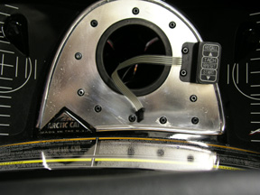
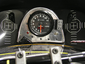
Step 10:
Remove Control Panel (Use Extreme Care When Working With Panel And Wires) And Use Rivits To Attach Panel To Plates.
See Picture 2.
Step 11:
Check Pin Settings. Settings Should Be As Follows:
Pin 1 - ON
Pin 2 - ON
Pin 3 - ON
Pin 4 - OFF
Step 12:
Place Control Panel Wire Through Hole In Plates, And Gently Push VDO Tach Through Hole. Plug Control Panel Back Into VDO Tach.
Step 13:
Place Rear VDO Cover Back On, Making Sure To Fead All Wires Through Hole. Use Cap Nuts To Tighten Cover Back On To VDO.
OPTONAL: Use A Bead Of Silicon Around Edge Of Cover To Help Seal From Any Dirt And Moisture.
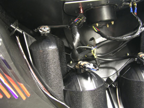
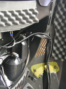
Step 14:
Wire Tach As Follows:
See Pictures 3, 4, And 5.
A. Solder Red And White VDO Tach Wires Together With Power Wire. This Will Power The Playback Function And Back Light Of The Tach. Run This Power Wire One Side Of
Switch. Use A Second Piece Of Electrical Wire To Run From Other Side Of Switch To Positive Battery Terminal. Place 1 Female Spade Electrical Connector On End Of Wire To Attach To Battery.
B. Solder Wire To Black VDO Tach Wire, And Run To Negative Battery Terminal.
IMPORTANT NOTE: Place This Wire And A Second Ground Wire In Female Electrical Connector. Place Eyelet Electrical Connector On This Second Ground Wire. Connect Eyelet To Chassis And Spade To Battery.
C. Solder (Scotch-Lock May Also Be Used) Green VDO Tach Wire To Yellow Wire In Stock Yach/Speedometer Harness.
Step 15: (OPTIONAL)
Check Engine Light Hook-Up
Use Dril And 1/2" Bit To Drill Hole In Plate, Making Sure To Not Drill Into Dash.
Step 15 A:
Push Red 12v Light Into Hole.
Step 15 B:
Solder (Scotch-Lock May Also Be Used) 1 Wire From Light To Brown Wire (Ground) From Stock Tach/Speedometer Harness. Solder (Scotch-Lock May Also Be Used) 2nd Wire From Light To Orange/White Wire From Stock Tach/Speedometer Harness.
Note: Additional Lights Can Be Hooked To Other Functions.
Function And Wire Color Listed Below.
Temperature Light - Red/White Wire
High Beam - Blue Wire
Low Oil Indicator - Red Wire
Step 16:
Make Sure Battery Is Charged And All Wires Are Connected.
Use Electrical Tape To Tape Over All Solderings, Connections, And Scotch-Locks. Also, Use ElectricalTape To Cover Stock Speedometer/Tach Plug. This Will Help Prevent Moisture And Dirt From Getting Into The Plug.
Step 17: (Mandatory!)
Get Out Mothers Polish And Rag, And Shine Aluminum Plate. Sit Back And Admire The Great Job You Did! See Picture 6.